

GG-DVI Install guide
GG-Video install guide:
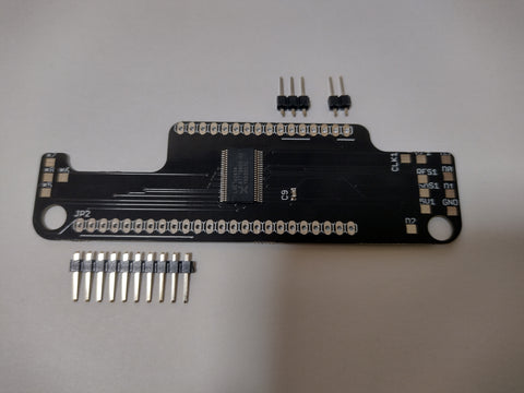
Your kit will include the following parts:

Before you begin assembly, connect a HDMI cable and a powered USB C cable. You should see both led's on the pcb illuminate and a test image on your display.

If you do NOT see this image, your monitor is NOT compatible with the video signal our kit produces. Please contact us via our Discord before proceeding any further, or test on another monitor. Update! There's a jumper you can solder to enable support for all monitors! see down below

If you see the above image, you are ready to assemble the PCB. Break away the pin headers as shown. You only need to solder the headers to the pads with the white line beneath them. You can solder more if you prefer.
When soldering the PCB, ensure you include the angle as shown below. This is so the Video socket clears the battery tray in the gamegear shell. The steeper angle, the better. Aftermarket shells are much thinner and this is not as important, but still recommended.

Once assembled, the PCB will slide over the lower screw posts and can be connected to your gamegear. There are many wiring options, depending what LCD screen you have installed. If you have a BennVenn IPS kit with ribbon installed, you can solder directly to the pads on the ribbon. If you don't, you can solder to the resistors near the ASIC (see our GG kit install guide for locations)

Below are the 10 connections you need to make.

Our helper board makes this job very simple in some builds.

We have added in debugging LED's. The 6 orange LED's in a row will illuminate under certain conditions. These are - LED #
- Illuminated when a CLK signal is detected
- Illuminated when a RES signal is detected
- Illuminated when a CL2 signal is detected
- Illuminated when both D0 and D1 signals are detected
- Illuminated when both D2 and D3 signals are detected
- Illuminated when the FPGA code is running.

The video format is DVI - 640x480 60hz.
GG video is integer scaled to 480x432.
SMS video is integer scaled to 512 x 392.
If your display is unable to frame lock to the GG's native frame rate, you can press and hold switch S2 to disable frame locking (You can solder these switch pins to force it to be always enabled)
Do not connect a USB C cable to the kit while installed in your gamegear. It will permanently damage the FPGA board trying to power your console.
As discussed in TheRetroChannel (Youtube) install video, by bridging this jumper all monitors and displays will recognise the GGHD video and allow frame locked video. If you are having issues, you can solder this pad circled in blue with a small piece of wire.
